 |
Prof. A.Gh PodoleanuHead of Applied Optics GroupProfessor of Biomedical OpticsIngram Building Rm.301 |
Del Mar Photonics featured customer
|
|
Prof. A.Gh PodoleanuHead of Applied Optics GroupProfessor of Biomedical OpticsIngram Building Rm.301 |
AP has joined the Applied Optics Group in January 1993 as a Tempus Fellow and then worked as a Research Associate since Sept. 1993. Up to 1992, he was associate professor in the Technical University Bucharest, Romania, where he taught Physics, Optics and optoelectronics and developed research on Lasers and fast optoelectronics. He was involved in Kent in research and development of a subnanosecond dwell time multichannel digital correlator (the fastest multichannel configuration), in distance measurements using white light interferometry, Faraday sensing and secure optical communications. Since 1995 he is been working in the optical coherence tomography (OCT) field for imaging eye and skin and flow characterisation. He contributed towards development of the en-face OCT imaging as a new technology to complement the more conventional longitudinal OCT imaging. For the first time, he generated dual OCT and confocal images of the retina. He is co-author of more than 150 journal papers and conference proceedings and of 13 patents on the above mentioned subjects. In 1984, he was awarded The Romanian Academy "Constantin Miculescu" prize for research in Lasers and Nonlinear Optics.
Related Del Mar Photonics products:
Del Mar Photonics - Adaptive optics (deformable mirrors) - Wavefront sensors - Complete adaptive optics system - Unimorph Deformable Mirrors part numbers
WAVEFRONT SENSORS: ShaH FAMILY
A family of ShaH wavefront sensors represents recent progress of Del Mar
Photonics in Shack-Hartmann-based technology. The performance of Shack-Hartmann
sensors greatly depends on the quality of the lenslet arrays used. Del Mar
Photonics. developed a proprietary process of lenslet manufacturing, ensuring
excellent quality of refractive lenslet arrays. The arrays can be AR coated on
both sides without interfering with the micro-lens surface accuracy. Another
advantage of the ShaH wavefront sensors is a highly optimized processing code.
This makes possible real-time processing of the sensor data at the rate
exceeding 1000 frames per second with a common PC. Due to utilizing low-level
programming of the video GPU, it is possible to output the wavefront data with a
resolution up to 512x512 pixels at a 500+ Hz frame rate. This mode is favorable
for controlling modern LCOS wavefront correctors.
The family of ShaH wavefront sensors includes several prototype models, starting
from low-cost ShaH-0620 suitable for teaching laboratory to a high-end
high-speed model, ShaH-03500. The latter utilizes a back-illuminated EM-gain CCD
sensor with cooling down to -100°C. This makes it possible to apply such a
wavefront sensor in astronomy, remote sensing, etc.
Specification Table for ShaH wavefront sensors:
| ShaH-0620 | ShaH-03500 | |
| Aperture dimension (diameter) [mm] | 6 | 3 |
| Number of subaperures for analysis | 1000 | 250 |
| Maximum tilt normal [rad] | ±0.05 | ±0.05 |
| Minimum measured curvature [m] | ±0.06 | ±0.03 |
| Repeatability RMS 2,3 | λ/100 | λ/100 |
| Absolute measurement accuracy RMS 2,3 | λ/25 | λ/25 |
| Relative measurement accuracy RMS 2,3 | λ/100 | λ/100 |
| Relative measurement accuracy P-V 1,2 | λ/20 | λ/20 |
| Tilt measurement sensitivity [rad] | 3E-6 | 5E-6 |
| Curvature measurement sensitivity [m] | 500 | 140 |
| Spatial resolution [mm] | 0.15 | 0.15 |
| Acquisition frequency [Hz] | 20 | 500 |
| Processing frequency [Hz] | 20 | 500 |
| Working wavelength [nm] | 400-1000 | 400-1000 |
| Calibrated waveband [nm] | 100nm | 100nm |
| Working temperature [0C] | +10 to +40 | 0 to +35 |
| Weight (max) [Kg] | 0.3 | 2 |
| Dimensions (LxHxW) | 155x55x55 | 258x174x139 |
Main features of the ShaH software:
Wavefront acquisition: Continuous or ext. trigger mode; absolute (factory
calibration) or referenced (user calibration) mode; background signal: save and
subtract in real time. The time history is only limited by the free memory
(approx. 50KB per frame). The stored data are available for retrospective
display, processing, and analysis.
Real-time functions and displays: Wavefront display (units: microns or waves):
3D plot; 2D projection; synthesized interferogram; Zernike polynomial
coefficients (up to 9th order); time history of 4 Zernike coefficients or
orders; RMS and PV phase error.
Point Spread Function measurement: PSF display: 3D plot; 2D projection.
Parameters: Strehl ratio; best focus plane; focal plane of ideal lens.
Retrospective functions and displays: All the functions available in real time,
plus:
Wavefront display: 3D plot, 2D projection, and XY profile without tilt and/or
focus and/or 3rd order aberrations; spot displacement map; residual zonal error
of modal approximation.
Pupil calculation: automatic or manual.
MTF display: 2D or 3D plot; XY profile; best focus plane; user specified plane;
focal plane of ideal lens.
Intensity display: 3D plot; 2D projection; XY profile; M² factor; intensity
profile at given distance
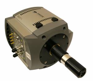 ShaH-03500 high-speed wavefront sensor |
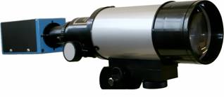 ShaH-0620 wavefront sensor with telescope |
Quantum Efficiency (QE) spectral curve for ShaH-03500 high-speed wavefront sensor
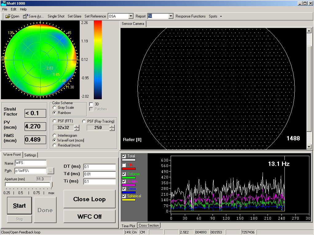
ShaH wavefront sensor software screenshot
UNIMORPH WAVEFRONT CORRECTORS
Del Mar Photonics has adopted and further developed technologies of mirror
manufacturing initially proposed in Adaptive Optics Laboratory of Lomonosov
Moscow State University. Recent advances in production technology allow us to
manufacture a variety of deformable mirrors with 30-60mm aperture diameter, good
surface quality, and record stroke for such type of the mirrors. With 30mm
aperture, the maximum measured stroke is 50um. Unlike membrane mirrors, this
type of wavefront correctors can bear an initial curvature. We have an
experience in manufacturing the mirrors with an initial radius of curvature of
500mm. The reflective surface of the mirror can be cleaned by means of a
conventional laboratory technique, which facilitates applications in university
labs. The mirrors are shock- and vibration-resistant. In comparison with bimorph
mirrors, our correctors demonstrate enhanced mechanical stability and better
reliability. The mirrors are well-suited for compensation of low order
aberrations (up to 4th order of Zernike polynomials).
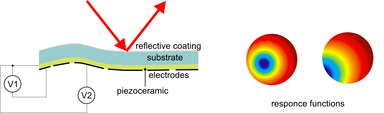
Principle of operation of unimorph mirrors
The unimorph mirror itself is constructed of a thin plate of piezo-electric
material coupled to a substrate plate. The electrode pattern is deposited on the
piezo-plate, which is then joined together with the substrate to form a sandwich
structure. The ground plane is the back surface of the substrate in the unimorph.
An optical surface is formed on the front surface of the substrate plate. The
polarization of the piezo-electric plate is chosen so that to make the plate
expand or contract when voltage is applied to the electrode. The differential
expansion/contraction of the substrate and piezo-plates causes the unimorph to
bend, much in the same way as a bi-metallic strip will bend when heated.
Typical electrode arrangement diagram for standard mirrors are
shown below:
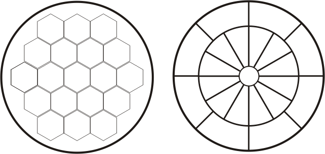
19 electrodes HEX-arrangement 21 electrodes MDL-arrangement
Typical specifications for unimorph deformable mirrors
Item Value
Substrate quartz, glass
Clear Aperture (diameter), mm 30-60
Stroke, μ 15-40
Number of control electrodes 13-36
Control voltage (max), V ± 300
Resonance frequency, Hz > 2000
Reflecting coatings protected Al, Ag, Cu, multilayer dielectric coating of
reflectivity ρ≥99%
Optical Damage threshold
in CW operation (up to), kW/cm²
in pulsed operation (up to), J/cm²
0.05
4
Surface quality (scratch-dig) 60-40
Hysteresis <15 %
Operating temperature range °C +10 +40
Storage temperature range °C -30 / +70
Weight (max), Kg 0.1
Size, mm Ô55x55
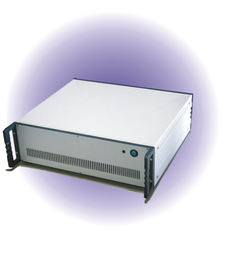 |
Control unit specification: Item Value Number of channels* (max) 32 Control interface USB Response delay (max), s 0.001 Output voltages, V ± 300 Control step, V 0.15 Standard frequency bandwidth at -3dB, 100nF load, Hz > 500 Operating temperature range °C -10 / +40 Storage temperature range °C -10 / +70 Weight (max), Kg 8 Size, mm 440x400x140 (19” rack mountable) Power supply 110-220V ; 50-60 Hz Cable length between the amplifier and the adaptive mirror (standard), m 5 • Several units can be connected to the host computer for control mirrors with more than 32 electrodes. • High voltage power supply is built in. Control Software: • Device drivers for Windows 2000/XP, diagnostic and control utility with graphic interface, SDK for C/C++. |
Some examples of mirror response functions measured with a Twyman-Green
interferometer at λ=632.8nm, 30mm aperture:
 Defocus: +100V |
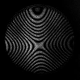 Astigmatism: +200V |
 Coma: +200V |
 Electrode #4 (outer ring): +200V |
For larger pictures check this pages:
defocus -
astigmatism -
coma -
arbitrary
Del Mar Photonics - Adaptive optics (deformable mirrors) - Wavefront sensors - Complete adaptive optics system - Unimorph Deformable Mirrors part numbers